 |
| We supply API certified oilfield drilling rigs, workover rigs, drawworks, wire rope, drill line, DC motor, AC motor, YM Hydranlic Catheads, ZP series rotary table, hydraulic winches, air winches, hydraulic power units, rotary hoses, crown block, sheave, traveling block, hooks, deadline anchor, top drive spare parts, drill pipe elevator, casing elevator, drill collar elevator, tubing elevator, sucker rod elevator, slip type elevator, single joint elevator, SE spider, links, perfection link, manual tong, casing tong, dies, power slip, manual slip, Kelly bushing, iron roughneck, power tong, hydraulic power tong unit, Kelly spinner, ram BOP, annular BOP, diverter, BOP control system, BOP control line, Conflex hose, spacer spools, adapter spools, double studded adapter flanges, drilling spool, choke and kill manifold, gate valves , butterfly valves, shale shakers, screens, desander, Centrifugal pumps, Vacuum degassers, Mud cleaners, Desilters, Shearing pumps, Centrifuges, Agitators, Mixing pumps, Poorboy degasser/Mud gas separator, screw pump, Venturi hopper, Submersible slurry pump, Flare igniter, Mud gun, Mud tanks, F-Series Triplex Mud Pump, 3NB Series Triplex Mud Pump, Unitized Mud Pump Package, Mud pump Spare parts such as Discharge Filter Assembly, Clamp of Mud Pump, Piston Assembly, Cylinder Head and Valve Cover, Guide plate, Plug Board Assembly, Air chamber assembly, Shear Relief Valve, Liner of Mud Pump, Cross Head of Mud Pump and Other parts Liner hanger, Cement head, Float collar and float shoe, Cementing plug, Casing Packer, Casing Centralizer, Mill shoe, Stop collar, Double pump cementing units, fracturing pumping units, Completion tools, pumping units, sucker rods, sucker rod pumps, screw pumps, submersible motors, X-mas tree, tubings, drill pipes, drill collars, heavy weight drill pipes, Kelly, stabilizers, drilling jars, bit subs, X-over subs, hole openers, casing and tubing drifts, casing scrapers, drilling instrument and electrical System, oilfield camp houses, drilling instrumentation and electrical system. Please send email to us if you need any information. |
|
| NJB-2 model mud pump Compound monitoring system |
|
Part one is digital display screen (including five display windows). It can display stroke/min, instantaneous pressure, maximum pressure, instantaneous displacement and accumulative displacement. The display adopts liquid crystal display (LCD) with automatic control back light source. Therefore, whatever the ambient light ray is strong or weak, it can display clearly.
Part two is working indicating light. The indicating light (in English and metric system) is on to indicate the current metering unit. The high pressure light is on to indicate that the slurry pressure is up to or exceed the setting alarm pressure. The over-pressure indicating light is on to indicate that the slurry pressure has exceeded the maximum setting pressure, and the system is in control condition. The over-pressure indicating light is flashing to indicate that the system is in control condition, and it is not over pressure or over-pressure last.
Part three is instrument key board. It consists of four keys: F1, F2, F3, F4. For detailed information, refer to related operation instructions.
4.1.2 Key functions at different conditions
Table 1: Single key function
|
Key
|
Starting up
|
Working
|
Setting
|
|
Time
|
F
|
T
|
F
|
T
|
F
|
|
F1
|
1S
|
ON
|
4S
|
Change model of unit
|
1s
|
Do not save the revised value and exit the setting condition.
|
|
F2
|
1S
|
ON
|
2S
|
A. Release control
|
1s
|
Change the digit position. (shifting)
|
|
5S
|
B. Pressure sensor is to O.
|
|
F3
|
1S
|
ON
|
4S
|
Pause/Begin to accumulate
|
2s
|
Save the revised value and exit the setting condition.
|
|
F4
|
1S
|
ON
|
2S
|
Clear the accumulative displacement
|
1s
|
Change the value of digit. (flashing position).
|
I.
General description
The NJB-2 model mud pump Compound monitoring system is used for monitoring the mud pump rpm, calculate and display slurry stroke, instantaneous displacement and accumulative displacement; calculate and display the instantaneous pressure of mud pump through monitoring the slurry pressure; and alarm and control the mud pump pressure in according to the set pressure alarm value and maximum value.
This system is suitable for installation on the mud pump with remote control box. Instruments on the mud pump control cabinet and on the remote control box adopt bus interface to transmit data and orders. And the Compound system of instrument can automatically estimate and define the main machine and auxiliary machine. Therefore, it is very convenient to install and operate the instrument on the mud pump with remote control box.
The instrument adopts high performance central processing unit (CPU), sensor, industrial grade IC module and other elements with high stability. Therefore, it is with good stability, high accuracy, strong interference killing features, etc. The housing of instrument is made of stainless steel with good strength, anti-corrosion, explosion-proof and water-proof performances. It is suitable for all kinds of harsh environments. Compound design of instrument is as per special environment and development direction of automatic control. It will be operated conveniently, installed freely and widely used with reliable performance in order to avoid unnecessary equipment damages and safety accidents, reduce your working load and increase the working efficiency.
II. Main functions description
2.1 Stroke and displacement metering system
The system will measure and display the mud pump strokes, instantaneous displacement and accumulative displacement. From the instrument, we can know the working speed and working capacity of mud pump clearly. The decimal point has automatic shifting function to make higher resolution factor of small displacement and extend range of large displacement. The maximum accumulative displacement can be up to 9999.9m3 or 2641.8kUSgal.
2.2. Pressure monitoring, alarming and control system
The system will measure and display the slurry instantaneous pressure and output related signal in according to actual pressure.
A. Alarm: when the slurry instantaneous pressure exceeds the alarm setting pressure value, the system will output an alarm signal; the external alarm unit will be audible and visual alarming and the high pressure indicating light will be on. Caution: the mud pressure is at high pressure condition. When the slurry pressure is lower than the value, the alarm will release automatically and the high pressure indicating light will be off.
B. Control: when the slurry instantaneous pressure exceeds the maximum alarm setting pressure value, the system will output an alarm signal and make the diesel rpm decrease to idle speed through a solenoid valve; meanwhile, the over-pressure indicating light will be on. Caution: the mud pressure is at over-pressure condition. When the slurry instantaneous pressure is lower than the maximum value, the over-pressure indicating light will be flashing. Press the F2 brake down for more than two seconds (it will be of no effect at over-pressure condition) to release the control signal and the over-pressure indicating light will be off.
Caution: Do not accelerate the diesel engine until the control signal is released.
2.3. Power supply and data transmission interface
The interface is not only power supply interface of auxiliary machine, but also data control transmission interface between the main machine and auxiliary machine. The auxiliary machine is display window and operation platform of main machine synchronization transmission remotely. (if you have not order the remote control system, the interface and related functions will be not provided.)
III. Main technical parameters
Display range of instantaneous pressure: 0.0Ą«999.9MPa or 0Ą«99.99kPsi
Maximum pressure setting range: 0.0Ą«99.9MPa or 0Ą«9.99kPsi
Display range of stroke: 0.0Ą«999 S.P.m (stroke/minute)
Display range of instantaneous displacement: 0Ą«9999L/min or 2642USgal/min
Measuring range of accumulative displacement: 0.00Ą«9999.9m3/min or 2641.8kUSgal/min
Digital display element: LCD displayŁšwith back light sourceŁ©
Pressure input signal: 4Ą«20 mA=0Ą«103.4MPa=14.5 kPsi
Power supply of pressure sensor: 20V / 30mA
Displacement input signal: pulsation
Measuring accuracy of displacement: 0.5Ł„»òĄÀ1 pulsation (LMS)
Control output: DC24V / 0.5A
Working power supply of instrument: DC24V
Self-exhausted horsepower of instrument: ŁŒ5W
Working environmental temperature: Ł20ĄæĄ«+70Ąæ
Environmental relative humidity of instrument: 15%Ą«95% Łšat 25 ĄæŁ©
Guarding grade of instrument: IP65
Anti-vibration capacity: maximum 2G, each 2 hours for triaxial direction
Anti- interference capacity: 1000Vp-p, pulse width 1 microsecond
IV. Operation instructions
4.1. General description
4.1.1 Figure 1 is schematic diagram of secondary gauge panel and it consists of three parts:
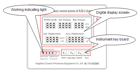
Figure 1: Instrument panel
4.3.3 Displacement setting
When the instrument is on, firstly, press the F1 key down with the F4 key, the instrument will enter ĄźĄŻ displacement setting valueĄŻĄŻ setting condition and all indicating lights will be flashing, as shown in figure 3:

Figure 3 Displacement setting
The setting method is the same as that of pressure setting. The setting digit will be flashing. Press the F4 key to select the digit, after selected, press the F2 key down to set next digit. After five parameters are finished, press the F3 key down for two seconds to save and exit. If do no save the setting, press the F1 key down for one second and exit the system.
Table 3: Current parameters of displacement, display position and setting value before delivery
|
Display parameters
|
Display position
|
Pre-setting range
|
Setting value before delivery
|
|
Measuring quantities of gears
|
Stoke display
|
0Ą«999
|
30
|
|
Speed reduction ratio
|
Instantaneous pressure display
|
0.0Ą«9.999
|
5.619
|
|
Quantity of plunger pump
|
Maximum pressure display
|
1Ą«3
|
3
|
|
Diameter of plunger
|
Instantaneous displacement display
|
0.0Ą«999.9
|
101.6mm
|
|
Stoke of plunger
|
Accumulative displacement display
|
0.0Ą«999.9
|
203.2mm
|
Note: The displacement value is stipulated according to related unitized components. Do not change it. If the unitized components are changed, the displacement value must be changed.
Table 2: Multiple-key functions
|
Multiple key
|
Time
|
Functions
|
|
Firstly F1Ł«F2
|
1s
|
Come into ĄźĄŻsetting alarm pressure and maximum pressureĄŻĄŻ setting condition.
|
|
Firstly F1Ł«F4
|
2s
|
Come into ĄźĄŻsetting displacementĄŻĄŻ setting condition.
|
|
Firstly F3Ł«F2
|
3s
|
Come into ĄźĄŻpressure measuring error correctingĄŻĄŻ setting condition.
|
|
Firstly F3Ł«F4
|
3s
|
Reset ĄźĄŻTheoretical value of pressure measuring error before deliveryĄŻĄŻ
|
|
F1Ł«F3
|
1S
|
OFF
|
4.2. Basic operations
4.2.1 Power on
After the power is on, the instrument is in ĄźĄŻOFFĄŻĄŻ condition and the system will not measure, control and display.
4.2.2 Starting
A. Press any key to start the instrument.
B. When the main and auxiliary machines are working at the same time, two machines should be on.
4.2.3. OFF
A. At working condition, press the F1 + F3 keys down for one second to shut down.
B. When the main machine is connected with the auxiliary machine, shut down one machine with keys and the other machine will be shutdown.
4.2.4. Change unit
At working condition, press the F1 key down for 4 seconds to change unit. The indicating light will indicate the current metering unit.
4.2.5. Release control
When the over-pressure control signal is output, and the slurry pressure is decreased to below the maximum pressure value (Ł0.2MPa or ĄȘ0.03Kpsi), press the F2 key down for two seconds to release control signal and turn off the over-pressure indicating light.
When releasing brake, if the digits on instantaneous pressure display and the maximum pressure display are flashing at the same time, indicate that the release brake canĄŻt be performed. (The pressure value canĄŻt be up to the release condition), or release is not required (without output control signal).
4.2.6 Pause/Begin to accumulate
At working condition, press the F3 key down for four seconds to pause or begin to accumulate displacement. When the accumulate displacement is paused, the digit on the display will be flashing.
4.2.7 Clear the accumulative displacement
At working conditions, press the F4 key down for two seconds to restart to accumulator the displacement.
4.2.8 Other conditions indicating
A. At working condition, the ĄźĄŻmetric systemĄŻĄŻ or ĄźĄŻEnglish systemĄŻĄŻ LED of auxiliary machine is flashing, indicating that the auxiliary is not connected well or it is in trouble.
B. At working condition, if the instantaneous pressure display is flashing, indicate that the pressure sensor of main machine is not connected or in trouble.
4.3 Parameter setting
4.3.1 Instructions
A. Use the instrument at the first time, related parameters must be set through the key board of instrument panel. Otherwise, use the setting parameters before delivery.
B. In order to ensure metering correctness, do not set parameters when the mud pump is working.
4.3.2 Alarm pressure value/maximum pressure value setting
When the instrument is on, it is easy to select the unit. Firstly press the F1 key down and then press the F2 key down, the instrument will enter into ĄźĄŻ alarm pressure value/maximum pressure valueĄŻĄŻ setting condition, at this time, the indicating light will show the unit (the metric and English unit can not changed in setting condition. After the setting is finished, the two parameters can be automatic conversation and save), as shown on figure 2:

Figure 2 Alarm pressure value setting
The instantaneous pressure display will display the last alarm pressure value; the maximum pressure display will display the last maximum pressure setting value, and the digit will be flashing. Press the F4 key to select the digit, after selected, press the F2 key down to set next digit. When setting the alarm pressure value, the high pressure indicating light will be flashing; and when setting the maximum pressure value, the over-pressure indicating light will be flashing. After all settings are finished, press the F3 key down for two seconds to save and exit. If do no save the setting, press the F1 key down for one second and exit the system.
Caution: when setting, the alarm pressure value should be less than the maximum pressure value; otherwise, the alarm pressure will be void. That is to say, the alarm value is the minimum value of the two parameters.
5.3 Installation of external audible and visual alarm
Figure 6 is the schematic diagram of external audible and visual alarm. When installation, only require to open a round hole (its diameter is 28mm) at the proper position of instrument box, tighten the nuts down. The plug of alarm connection line should be interted into the output socket of alarm.
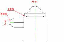
Figure 6 Schematic diagram of audible and visual alarm
5.4 Connection of secondary gauge, sensor and control box and between secondary gauges
5.4.1 Matched plug of the connection socket, as shown in figure 7:
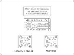
Figure 7 Schematic diagram of instrument back plate
5.4.2 The connection line terminal, color and function are as follows:
Power supply, signal, control connection lineŁš12-core plug, only the main machine is equippedŁ©:
1 terminalŁšredŁ©: power supply of main unitŁš+DC24VŁ©
2 terminalŁšorangeŁ©: power supply of pressure sensorŁš+DC19.5VŁ©
3 terminalŁšyellowŁ©: displacement signal +
4 terminalŁšgreyŁ©: Communication I
4.3.4. Pressure measuring error correct
When the instrument is on, it is easy to select the unit. Firstly press the F3 key down with the F2 key for two seconds, the instrument will enter into ĄźĄŻpressure measuring error correctĄŻĄŻ setting condition, at this time, the indicating light will show the unit (the metric and English unit can not changed in setting condition. After the setting is finished, the two parameters can be automatic conversation and save), the high pressure and over-pressure indicating lights will be flashing at the same time, as shown on figure 4:

Figure 4 Pressure measuring error correct setting
The pressure measuring error correct adopts two-point correcting method. The operator can choose any two points to correct. The system requires the first point is ĄźĄŻlow end correctĄŻĄŻ, and the second end is ĄźĄŻhigh end correctĄŻĄŻ.
Input ĄźĄŻ low end correctĄŻĄŻ position (pressure) into the instantaneous pressure display; and input the correct value into the maximum pressure display; input ĄźĄŻhigh end correctĄŻĄŻ position (pressure) into the instantaneous displacement display; and input the correct value into the accumulative displacement display.
The setting method is the same as that of pressure setting. The setting digit will be flashing. Press the F4 key to select the digit, after selected, press the F2 key down to set next digit. The high pressure and over pressure indicating light will be flashing at the same time. After five parameters are finished, press the F3 key down for two seconds to save and exit. If do no save the setting, press the F1 key down for one second and exit the system.
When entering setting, the ĄźĄŻlow end correctĄŻĄŻ point is zero point and the ĄźĄŻhigh end correctĄŻĄŻ point is full range value.
Before delivery, the full range value is 103.4MPaŁš15000psiŁ©. Firstly press the F3 key down with the F4 key for two seconds to renew the setting value.
Caution 1: When setting, the two input value of ĄźĄŻlow end correctĄŻĄŻ are both less than two input values of ĄźĄŻhigh end correctĄŻĄŻ, otherwise, the setting is void.
Caution 2: The choosing points of ĄźĄŻlow end correctĄŻĄŻ and ĄźĄŻhigh end correctĄŻĄŻ should be as two ends of pressure sensor to ensure linearity correct at full range.
4.3.5 The pressure sensor of main unit is to ĄźĄŻ0ĄŻĄŻ.
When the instrument is on, if the current value of pressure sensor is at 3.8mAĄȘ5.0mA (the current value should be based on the secondary measurement), and the system has no control output. Press the F2 key down for five seconds and the current value should be set at pressure measuring ĄźĄŻ0ĄŻĄŻ point.
During setting pressure measuring ĄźĄŻoĄŻĄŻ point, the instrument works normally. Only the instantaneous pressure display and maximum pressure display flash alternatively, indicating that the pressure sensor is to ĄźĄŻoĄŻĄŻ.
After the setting is finished, enter into the ĄźĄŻDo not release control conditionĄŻĄŻ, indicating that the pressure sensor is to ĄźĄŻ0ĄŻĄŻ correctly. Release key to return to normal condition.
During setting pressure measuring ĄźĄŻoĄŻĄŻ point, if the instrument returns to normal working condition directly, indicating that the pressure sensor to ĄźĄŻ0ĄŻĄŻ is void.
Caution 1: the pressure sensor to ĄźĄŻ0ĄŻĄŻ is only suitable for main unit, not for auxiliary unit.
4.4. Main unit and auxiliary unit operation
4.4.1 Installation and connection refers to 5.3.
4.4.2. Any of secondary gauges can be used as main unit or auxiliary unit.
The main unit and auxiliary unit are distinguished by connection lines.
The auxiliary unit can not work independently.
4.4.3 In generally, the main unit is installed on the control cabinet of mud pump, that is to say, the sensor is connected with the instrument. The main unit can work independently.
4.4.3 When using the main unit and auxiliary unit, the two units can be opened and closed each other.
4.4.4 When using the main unit and auxiliary unit, the auxiliary unit is display figure of main unit. That is to say, all display data and conditions of auxiliary unit is from main unit (control is output by the main unit). So, the power supply of main unit must be connected.
4.4.4 When using the main unit and auxiliary unit, the auxiliary unit is operation platform of main unit.
All operations of main rig are only for itself.
All operations of auxiliary unit are for itself and main unit. The ĄźĄŻpressure measuring error correctĄŻĄŻ of auxiliary unit is only for main unit.
4.4.5 When the main unit is setting parameters, the display of auxiliary unit is flashing. Do not allow to operate the auxiliary unit.
V. Installation
5.1 Installation of secondary gauge
The instrument adopts hanging type installation. We will provide proper installation methods according to your needs.
Size of instrument (mm): 210ĄÁ170ĄÁ72
Opening size (mm): 165x125
Size of installation hole (mm): 186ĄÁ100ĄÁ§¶5.5-4
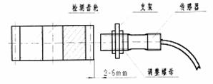
5.2 Installation of sensor
The installation method of sensor will be confirmed in according to detailed actual conditions. Install the sensor and connection lines at hidden places. In order to ensure the rate accuracy, the clearance of rpm (displacement) sensor and rate gear should not exceed 4mm, as shown on figure 5:
 5 terminalŁšgreenŁ©: pressure signal 4Ą«20mA 5 terminalŁšgreenŁ©: pressure signal 4Ą«20mA
6 terminal (blue): over-pressure control outputŁš+DC24VŁ©
7 terminal: for main machine, 7 and 8 terminal are connected.
8 terminal: for main machine, 7 and 8 terminal are connected.
9 terminalŁšpurpleŁ©
10 terminalŁšblackŁ©: power supply of main machine
11 terminalŁšwhiteŁ©: communication Ł«
12 terminalŁšbrownŁ©: displacement signal Ł
The secondary gauge is equipped with special signal connection lines. So only need to connect the special connection lines of main and auxiliary secondary gauges directly according to colors of connection lines. And the secondary gauge has automatic identification functions. The secondary gauge connected with sensor can be used as main unit, and the secondary gauge connected directly can be used as auxiliary unit. The auxiliary unit does not require connecting other lines.
When replacing spare parts, use our spare parts and install them according to instructions of our serviceman.
VI. Trouble shooting
6.1 The pressure is not correct or stable, or is zero
Realign the sensor (refer to 4.3.5). Check the pressure sensor for proper installation. Check the power supply plug of sensor is disconnected or broken or not. Check the orange line of sensor has DC19.5V voltage or not.
6.2 The display will be displayed when the mud pump doesnĄŻt work.
Check the displacement sensor, cables and sensor plug for proper connection.
6.3. The displacement doesnĄŻt display correct when the mud pump is working.
Check the displacement parameters to see that it is right. Check sensor for proper installation (the clearance of sensor and rate gear should not exceed 4mm). Check the induced magnetic steel of sensor is worn or not.
6.4 The alarm and output indicating is not right when using the auxiliary unit.
Take the plug out and check there is DC24V power supply or not between I and 10 terminal.
Check setting of main unit and auxiliary unit. Refer to section 4.4.
6.5 Control and alarm is abnormal.
Check setting of main unit and auxiliary unit. Check output voltage is DC24V or not when using the external alarm unit.
If you have any question, contact us.
VII. After-sales services
We will provide one-year maintenance on free and lifetime maintenance services. The technical department will supply instrument installation and technical support during operation at any time.
VIII. Notes in order
The following items shall be noted in order:
8.1 Installation type of second instrument
8.2 Power supply for control box
8.3 Installation type of sensor and length of connection lines
8.4 Instrument alarm and external alarm
8.5 Connection lines of instrument and control box
8.6 Technical parameters of sensor
|
|
PreviousŁș
Elevator
NextŁș
weight indicator system
Back |
 |
| VisitŁș timeŁș2017/4/26 ĄŸPrintĄż ĄŸcloseĄż |
|
|
|
|